| DIY speakers amplifiers design loudspeaker design amplifier DIY DIY DIY super high quality real Hi-Fi studio quality home studio recording engineer enjoy feast revel audiophile extra natural sound detailed open unmasked perfect sound music lover lovers studio monitors home cinema entertainments | ||||||||||||||||||||||||||||||||||||||||||||||||||||||||||||||||||||||||
|
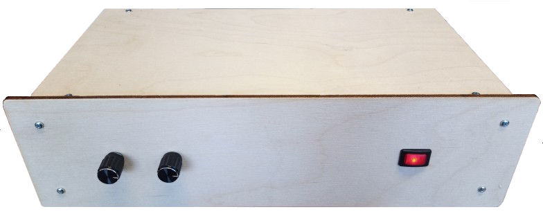
How to (easily!) build your own Poweramp 5 power amplifier
using the PA5L component kit with ready-cut cabinet parts.
(For info about the kit itself and how to get it, click here.) This
is a long webpage because these are step-by-step instructions. The
amplifier is very simple to assemble. Start by attaching two of the four
mounting blocks to the front using the mid-length screws.
The wide long slot is turned upwards with she square hole of the front to the left, like this: 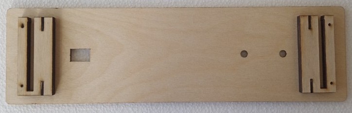 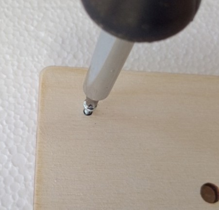
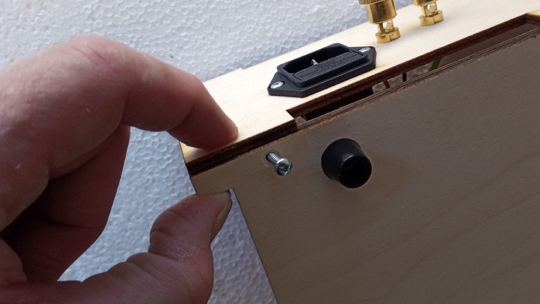
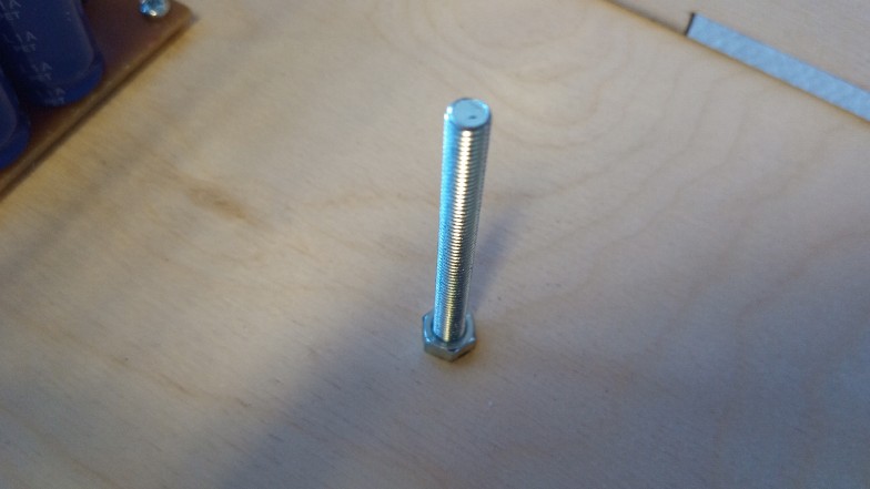
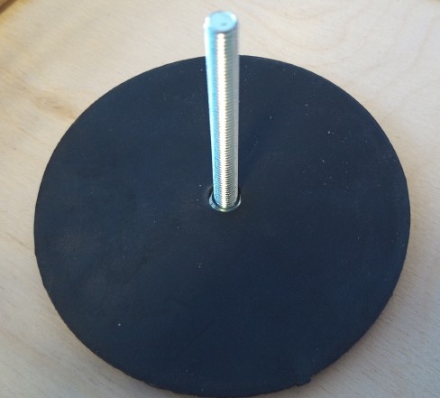
Do the same thing with the back, also here noticing the way the blocks are turned: 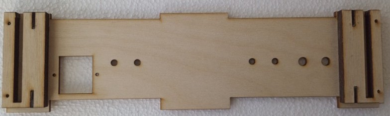 After this, take the bottom part and fix the rubber feet using the short screws: 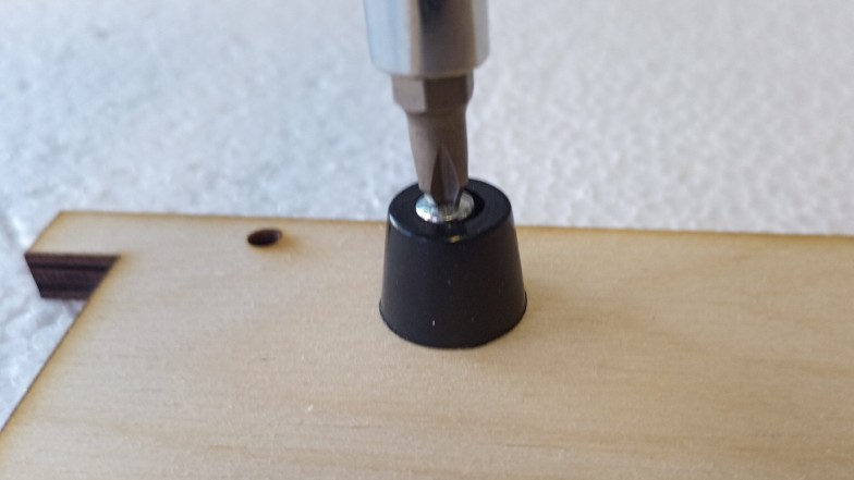 The distance between the upper rubber feet and their border (where the back panel will be placed) is slightly shorter than between the lower rubber feet and their border (where the front will be placed). 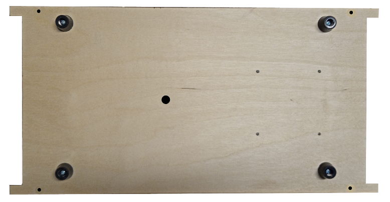
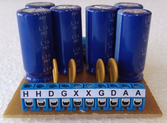
Start with the rear panel where the inputs and outputs are to be mounted, first fastening the RCA terminals. First, separate the parts. (Both the black/white and the black/red RCA terminals and their cables): 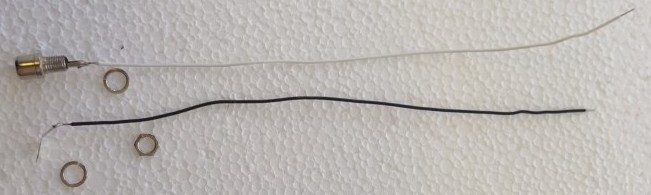 Place the black (= left) terminal in the hole closest to the edge like this. (When the back panel is in place, and you look at the amplifier from the front, the black terminal will be to the left.) 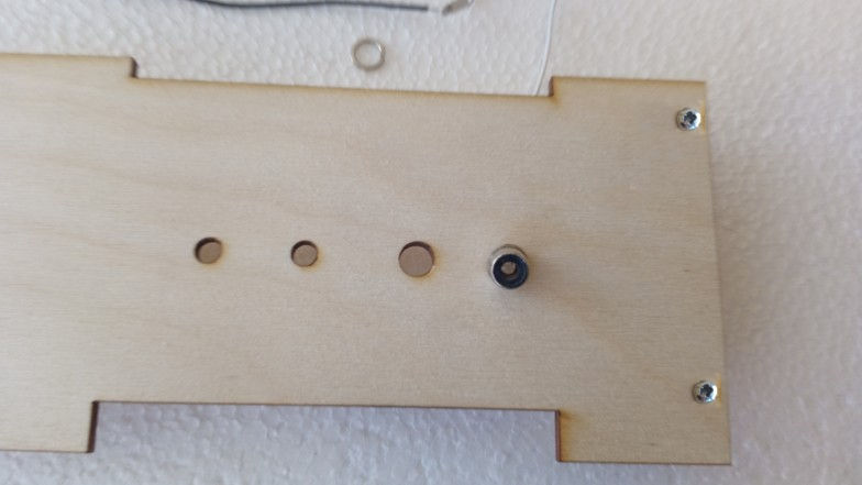 On the inside, first put the black cable with its ring contact in place, the hole closest to the edge. 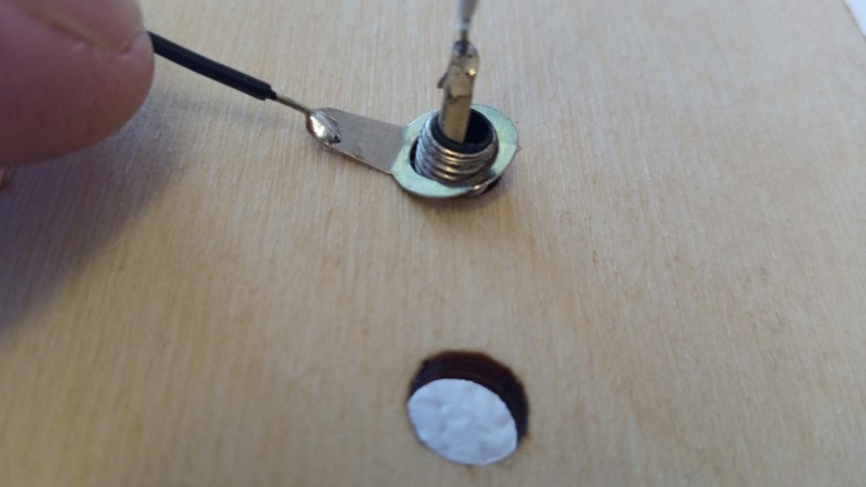 Then the spring washer... 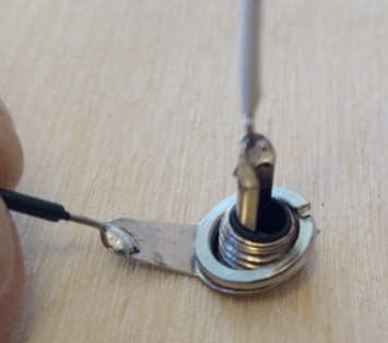 ...and then the bolt. First use your fingers, not any tool, until it takes threads properly. 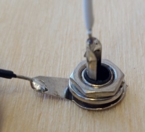 Then use pliers to tighten, but not too hard! When the spring washer becomes flat it is enough. Too hard and you might damage the thread.  Then do the same with the red RCA terminal. After this, twist the wires together like this: 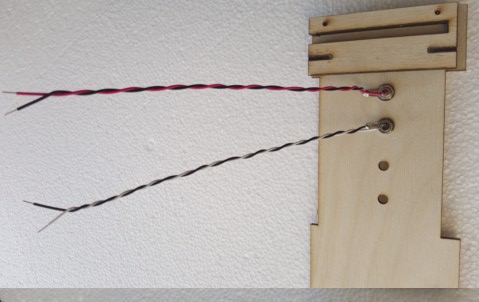 There are also four thin wires like these in the kit: One white short wire, one long red wire and two black wires, one short, one long. Twist the short wires (black and white) together like you did with the wires from the RCA terminals. Then do the same with the long wires (black and red). These will be used later, when connecting the volume control potentiometers to the amplifier modules. Now, mount the speaker terminals onto the back panel. To make it easier to get the holes for cables vertical, use something with 4 mm diameter to hold the terminals... (We happened to have a 4 mm drill which we screwed in place like this.) 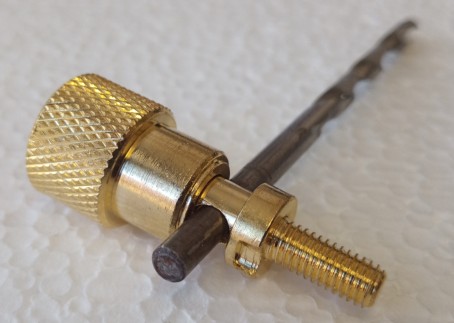 ...and hold it so that the hole becomes vertical when fastening the terminals: 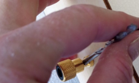 The normal placing is black terminals in the middle and red terminals outside, like this: 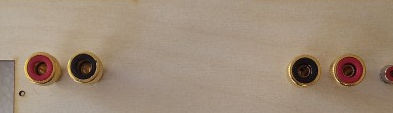 Mount the speaker terminals from the outside, and fit the rest in this order: First the cables with ring contacts. Black wires to black terminals and red to red, of course. Remember to hold the 4 mm (drill or whatever) so the holes of the terminals become vertical as in the picture above the previous picture. 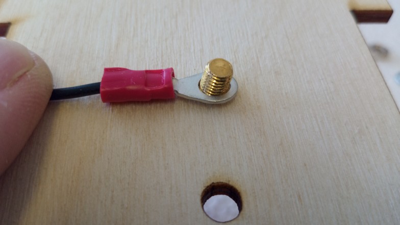 Then the flat washer, then the spring washer and finally the bolt: 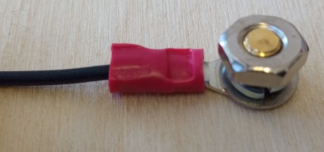 Tighten the bolt until the spring washer becomes almost flat: 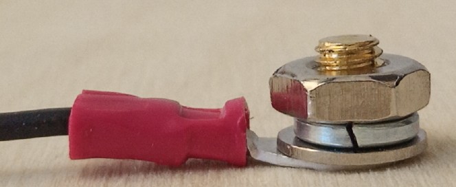 Now you attach the power input socket, contacts up, fuse holder down like this, using two of the short screws. 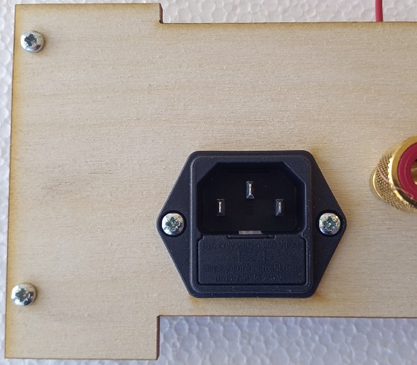 (Fuse: 5 x 20 mm, 1.6 A slow burn fuse for 220-240VAC, 3.2 A for 110-127 VAC.) The fuse is only included in the kit with the 230V transformer. After this, the rear panel is ready, put it aside for now. Wiring of the Power Supply Unit PCB:
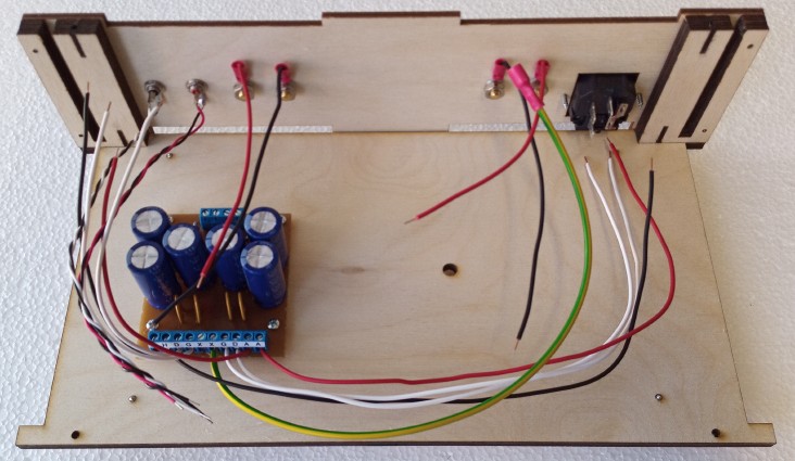
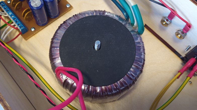
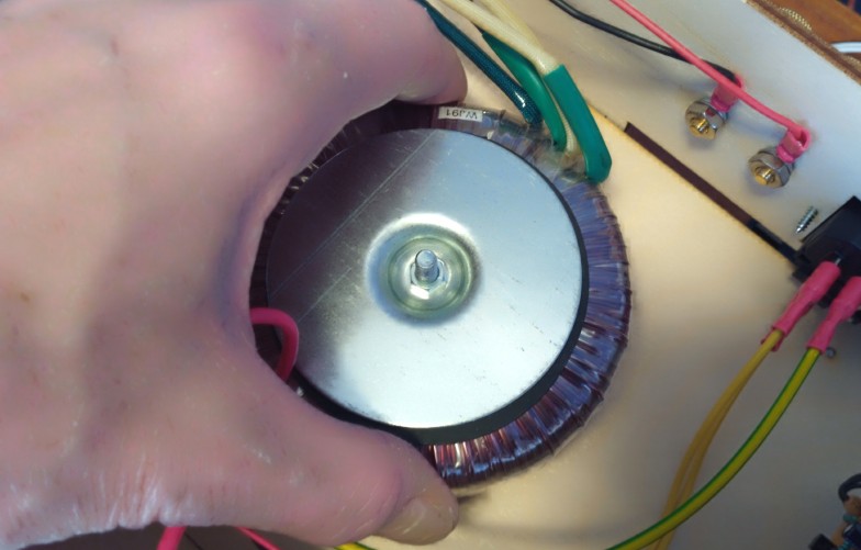
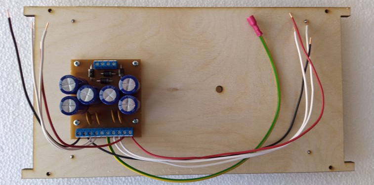 So this is the bottom panel, seen from above. Left = left, right = right, up = back, down = front. We recommend that you don´t fasten the mains transformer until later even if you could do it now. The transformer is relatively heavy and makes handling more difficult at this stage.
NB. If you bought the PA5L kit (without the transformer) the transformer you buy from someone else will not be marked the same way. See the very last part of this page.
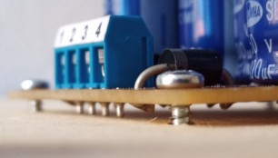
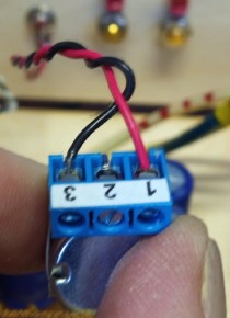
Now, connect the four stiffer wires (secondary voltage) from the transformer to the 4-way screw terminal of the PSU board. If the transformer was included in the kit, they are marked with 1 - 4 lines or dots. Connect the wire with one dot to no 1, the wire with two dots to no 2, the wire with three dots to no 3 and the wire with four dots to no 4. (If you have bouth the transformer locally, one secondary winding goes to 1 and 2, phase marking to no 2, the other secondary winding to 3 and 4, phase marking to no 4. See special instructions about the transformer at the end of this page. 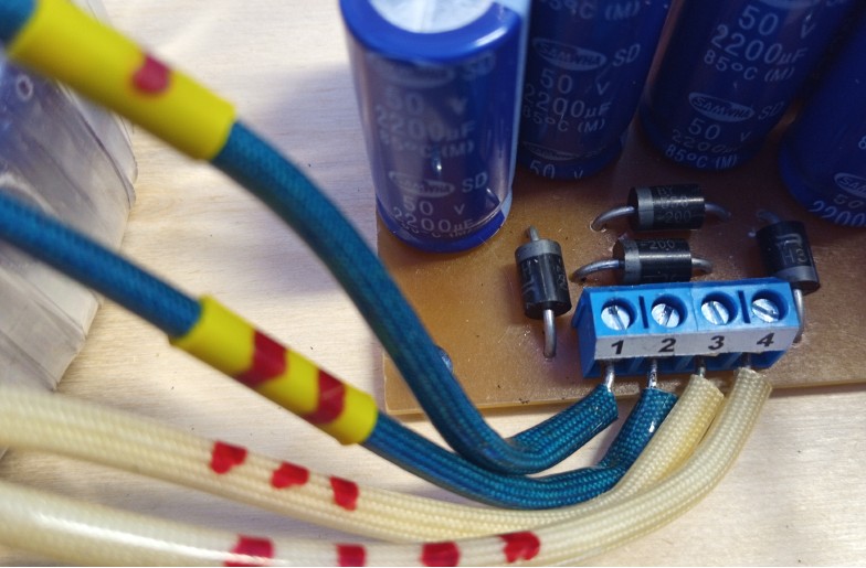
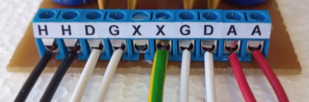
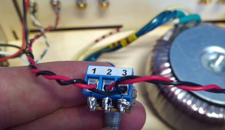 Here you see the right channel wiring (red and black). The left channel is exactly the same, but the wires are black and white (and the pair to 2 and 3 is also shorter).
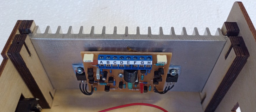
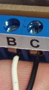
As you can see, both modules have a screw terminal marked A-B-C-D-E-F-G-H A, D, G and H are connected to the same letters on the PSU board. Here we show you right module, but the left module is connected the same way. The only difference is the colour of the wire going to the B terminal. It is red on the right module, but white on the left module First the red wire from A on the PSU board to A on the module. (Shorter to the left module, longer to the right, of course). 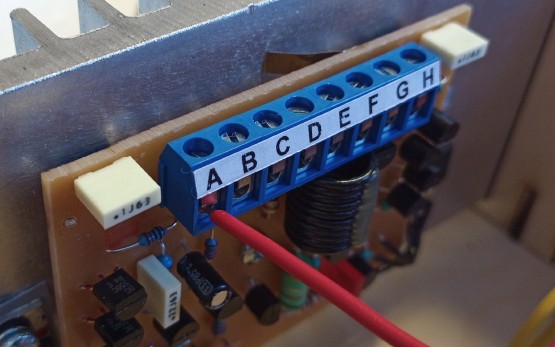 From the right volume control you have a red+black wire pair (right channel). Connect the red wire to B and the black wire to C. 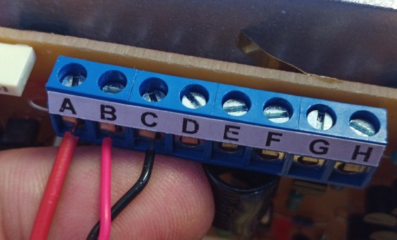 Then the white wires from the PSU board. D to D and G to G. Then the black wire from the PSU board (H) to H. 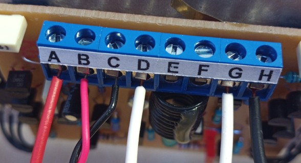 Finally, the wires from the loudspeaker terminals. Red to E, black to F: 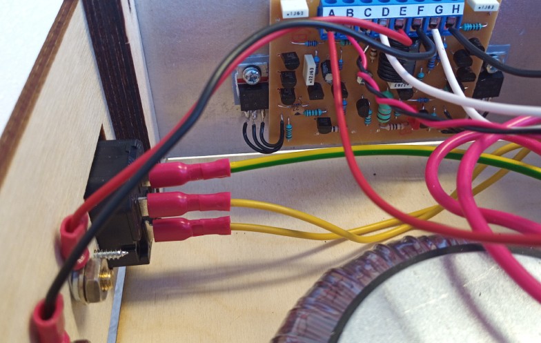
Now all electric and electronic components are in place and connected. It is time to put the volume control knobs in place. If both both volume control potentiometers have their terminals straight upwards, this is the way to get both volume control knobs right: Turn the slot of both potentiometer shafts as horizontal as possible. Here we have put a metal ruler in he slots, so they get almost perfectly horizontal. Then we remove the ruler, being careful not to turn the shafts while doing so. (If you don´t have a ruler this thin, you can use a knife or similar, of course.) Then, just push on the knobs with the index pointing straight up. (Both, of course, this is just to show the slot of the left potentiometer shaft.) 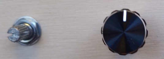 Now you are ready!!! Everything is in place, all wires connected. So, just plug in the AC cable, connect your sound source and you are ready to go -- or maybe not? PLEASE check all wiring again. Here is a checklist:
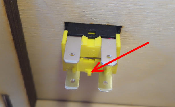
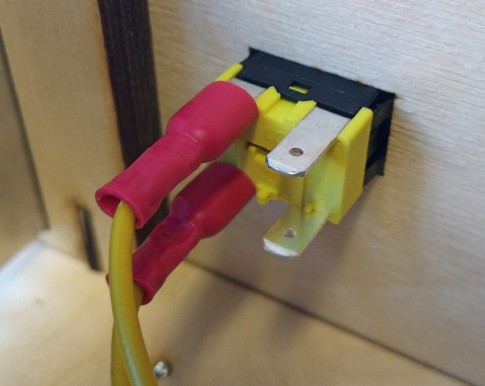
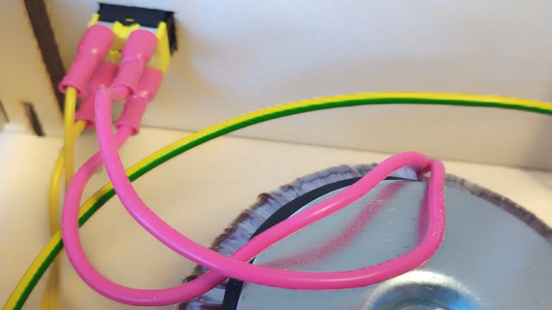
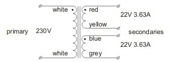
Everything was OK? Then screw on the top panel, connect the sound source (preamplifier, CD- or DVD player, computer earphone output (green socket), DAC or whatever with 0.9 V (or more) output signal. Then the loudspeakers (8 - 16 Ohm) and finally the AC cable. First set the volume controls low (about 9 o´clock position) and switch on the amplifier. With an active sound source, the sound should come within a fraction of a second. If both loudspeakers play music, it is OK to increase the volume. The modules are of course carefully tested before delivery, so if the wiring is correct, the amplifier will work perfectly. If there is no sound or only on one channel works, turn off the amplifier directly and re-check the wiring. If something is wrong, it has to be a wiring problem. Or, maybe, the loudspeakers. If you can measure resistance, loosen the loudspeaker cables and check so the resistance of the loudspeakers with cables attached is c:a 6 - 8 Ohm. If it is close to zero, the loudspeaker or cable has a short circuit and must not be connected to the amplifier. If there is something wrong and you cannot find what is wrong, just take a few photos of the inside of the amplifier and send them to us by email, and we will help you out. However, when this was written we have sold quite a few kits, and so far not one has failed, and if you follow the instructions above (especially the wiring list) nothing should go wrong. If you bought the PA5L kit, without the mains transformer it is important you identify the windings. You should have a label on the transformer or a data sheet, showing the markings of the primary and secondary windings First of all, the primary windings. They are usually thinner than the secondary windings because they carry less current. Clamp the two red female contacts onto the wires, so they can be attached to the power switch. Polarity is not important. Then identify the secondary windings, and this is important. Here are a two samples: |
||||||||||||||||||||||||||||||||||||||||||||||||||||||||||||||||||||||||
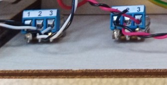
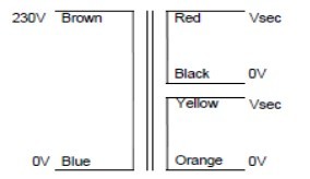  The polarity can be shown in
different ways: On the left picture it is 0 and Vsec (which can be for
example 22 or 24 V), on the right a black dot is indicating polarity.
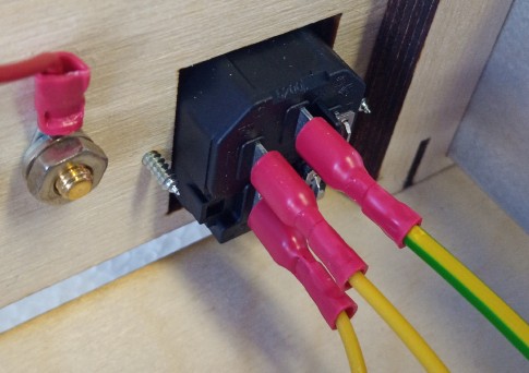
Primary voltage (in these cases 230 V) polarity is not essential, but the secondary polarity is very important. Here we have the same transformers, connected to the input screw terminal on the PSU board. 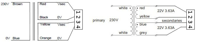 And the polarity marked wire from each one "polarity wire", and the other wire "non polarity wire". Then the 1 - 4 screw terminal is connected like this: 1 Winding 1, polarity wire (red on the left transformer, red on the right transformer). 2 Winding 1, non polarity wire (black on the left, yellow on the right) 3 Winding 2, polarity wire (yellow on the left, blue on the right) 4 Winding 2, non polarity wire (orange on the left, grey on the right. (As you see, colours are not the same, there is no standard.) On the INDEL transformers we use both wires from the same winding has the same colour, and both ones from the other winding another colour. And the polarity is indicated by a short plastic tube close the the transformer body: 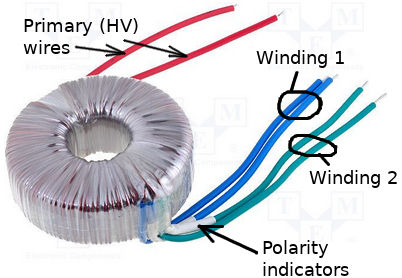 In this case this is one way to connect: green with polarity tube to 1, green without polarity tube to 2, blue with polarity tube to 3, blue without polarity tube to 4. However, forget the exact colours, Indel changes them every production cycle. The only thing that seems constant it that the primary voltage wires are red. (So far...) If you have bought the PA5C kit, you don´t have to worry about this, as we mark the secondary wires with one, two, three and four lines. And you just connect the wire with one line to 1, the wire with two lines to 2, three lines to 3 and four lines to 4. It couldn´t be more simple. © Valulutronic, Sweden 2019
|